Tutorial Effects - Texture Coordinates
TOC: Of Effects and Shaders
Back: Manipulating Colors
Next: Neighbouring Pixels
As we've seen before, the displaying of a texture involves texture coordinates:
float4 col = tex2D(Samp, In.TexCd);
The tex2D function takes 2 parameters: the sampler and a float2 that holds the two-dimensional texture coordinate at which the sampler is to be sampled. Texture coordinates range from (0,0) top-left to (1,1) bottom-right. And instead of x and y the two components of the vector are often referred to as u and v. For more details see: msdn about Texture Coordinates.
If we leave the In.TexCd parameter as is we are using the unchanged texture coordinates for every pixel drawn as they are being provided by the vertex-shader. A texture-coordinate can be provided per vertex and the graphic-card will do the interpolation between given per-vertex-texture-coordinates for every pixel of a mesh.
Visualizing texture coordinates
Just for getting an understanding of the texture coordinates lets visualize them. As their range is between 0 and 1 just like the individual color components of a float4, in the pixelshader function we can simply write:
return float4(In.TexCd, 0, 1);
to visualize the u component of the coordinate as red and the v component as green.

Shifting the x coordinate
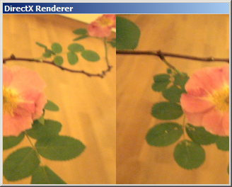
So lets see what happens if we modify the coordinates before using them in the tex2D function:
float2 cord = In.TexCd;
cord.x += 0.5;
return tex2D(Samp, cord);

Here for every pixel the x (i.e. u) component of the texture coordinate is offset by 0.5 which results in the texture being shifted by half its size on the mesh. And you see that where the texture coordinates are bigger than 1 (i.e. 1 to 1.5 in our example) the texture is being sampled in a way that we see a mirror effect.
Sampler States
This is where the sampler comes into the game. If you scroll to the top of the effect code you should see the following lines of code, which define the sampler:
-
sampler Samp = sampler_state //sampler for doing the texture-lookup
-
{ -
Texture = (Tex); //apply a texture to the sampler
-
MipFilter = LINEAR; //sampler states
-
MinFilter = LINEAR;
-
MagFilter = LINEAR;
-
};
The sampler states define how the texture is being sampled. Where the filters define interpolation modes between two pixels the address states define how texture coordinates beyond 0 and 1 are being interpreted. Try for example the following code:
-
sampler Samp = sampler_state //sampler for doing the texture-lookup
-
{ -
Texture = (Tex); //apply a texture to the sampler
-
MipFilter = LINEAR; //sampler states
-
MinFilter = LINEAR;
-
MagFilter = LINEAR;
-
AddressU = WRAP;
-
};
Save and see how the texture is now wrapped instead of mirrored. For a listing of all possible samplerstates check Effect States (Direct3D 9)
Texture Ripple
In the above example we are shifting the x coordinate of every pixel with the same amount. Here is an example that shifts the x coordinate depending on the value of the y coordinate to achieve a ripple effect:
float Frequency = 10;
float Phase = 0;
float Amplitude = 0.1;
float4 PS(vs2ps In): COLOR
{
    float2 cord = In.TexCd;
    cord.x += sin(cord.y * Frequency + Phase) * Amplitude;
    float4 col = tex2D(Samp, cord);
    return col;
}

Try an LFO (Animation)s output multiplied by 2 Pi (use the PI (Value) ) on the Phase to see the wave smoothly animated. The 2 Pi are needed here since the sin() function takes the angle parameter in radians which have a range from 0 to 2 Pi. In order to map the LFOs output (0..1) to that range we simply multiply by 2 Pi.
Function Printing
Or consider the texture coordinates as a 2d field you can use to plot a mathematical function, without any texture input:
int Frequency = 50;
float Phase = 0;
float Amplitude = 1;
float4 PS(vs2ps In): COLOR
{
    float2 cord = In.TexCd - 0.5;
    float dist = sqrt(pow(cord.x, 2) + pow(cord.y, 2));
    float4 col = sin(dist * Frequency + Phase) * Amplitude;
    col.a = 1;  //make sure the alpha component is 1
    return col;
}

Here the distance of every pixel to the center is computed and taken as input for a sine function.
Si claro so far?
Next: Neighbouring Pixels
Back: Manipulating Colors
TOC: Of Effects and Shaders
anonymous user login

Shoutbox
~1d ago
~9d ago
~17d ago
~1mth ago
~1mth ago
~1mth ago
~2mth ago
~2mth ago